iterm2 arrow keys not working in cursor application mode

By   February 3, 2016

(TL;DR at the bottom)

This is one of those things that irritated me for ages.  I generally don’t use arrow/home/end keys for anything except when I run (rarely) certain applications like ‘make menuconfig’ where I’m forced to navigate using arrow keys.

For the longest time, the arrow keys didn’t work on iterm2 in certain applications.  After digging in, I discovered the problem.

Ages ago, I started using OS-X, but terminal.app sucked so I installed iterm.  Then iterm2 came out and I upgraded.  Sometime thereafter I discovered the arrow keys didn’t work.  This morning, I decided enough was enough and I got to the bottom of it.  One of the answers on this question posted a handy little script to test whether the keys work in cursor application mode:


sh -c "$(cat <<\EOF
noecho_appmode() {
  stty -echo
  printf '\033[?1h'
}
modes="$(stty -g)"
restore_echo_and_appmode() {
  stty "$modes"
  printf '\033[?1l'
}
printf '\nType <Up> <Down> <Right> <Left> <Control-D> <Control-D>\n'
printf '(no output until after the first <Control-D>, please type "blindly")\n\t'
noecho_appmode             ; trap 'restore_echo_and_appmode' 0
cat -v
restore_echo_and_appmode   ; trap ''                         0
printf '\nExpected:\n\t'
printf 'kcu%c1\n' u d f b | /usr/bin/tput -S | cat -v
printf '\n\n'
EOF
)"

This told me that iterm2 wasn’t working correctly. But it obviously works for many other people.

TL;DR:


When I upgraded from iterm to iterm2, my settings survived and Preferences->Profiles->Keys (NOT Preferences->Keys) contained overrides for the arrow keys and home/end.  Once I loaded a Preset for “xterm default”, exited iterm2 and restarted it, arrow keys worked fine.


Delightful find!

By   January 21, 2016

Friend Mike sent along this Hackaday link on reverse engineering of some cheap chinese digital radio.  Since I dabble in digital radios at work it was of particular interest.  That article led me to downloading an issue of PoCk||GTFO which I had never encountered before.  A publication dedicated to reverse engineering or a glimpse into what the infinite monkeys are up to.  The writing is curiously delightful, most especially in the article on hacking a digital pregnancy test, e.g,

You can either look up the battery type to confirm it’s 3V, or just read the CE-mark label on the outside of the DPT that lists the part number, lot data, confirmation that this test is made by SPD GmbH out of Geneva, Switzerland (made in China), and that the test runs on 3V DC. Safety first, kids.

I spent my ‘hack time’ this morning reading this. [Aside: Usually I don’t allow myself the pleasure of ‘reading the internets’ in the mornings since I am smartest at 5AM and then become progressively more stupid as the day goes on.  By 21:30, I’m a drooling sack of meat barely capable of walking up the stairs to bed.   So I want to use my smart time for haxx0ring before I have to put it all down and head to work.]

Some christmas leds

By   December 1, 2015

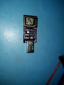
Working on a sort of secret-santa gift for members of my truck club, I decided to do something with the WS2812B RGB LED’s. There’s a metric buttload of blog articles about these so I thought I would try to add something.

From what I can see, people are spending a lot of time dealing with timing. Nodemcu can do it but not if WIFI is enabled; or at least reliably anyway.. Since I’d had some success with the hardware SPI on the ESP8266 talking to a thermocouple amplifier, I thought I would try to get the SPI hardware to do my bitbanging for me. Turns out it’s actually quite trivial and ‘just worked’. Thanks to Joost Damad for the pattern which saved me the effort of figuring it out myself. Isn’t the internet amazing? Whenever you get a bright idea, turns out someone’s already done it.

First initialize the hardware SPI interface per David Ogilvy’s blog:

bool
ICACHE_FLASH_ATTR
ws2812b_init(void)
{
        if (initialized || sysCfg.board_id != BOARD_ID_PHROB_WS2812B)
                return true;
        spi_init_gpio(SPI_DEV, SPI_CLK_USE_DIV);
        spi_clock(SPI_DEV, SPI_CLK_PREDIV, SPI_CLK_CNTDIV);
        spi_tx_byte_order(SPI_DEV, SPI_BYTE_ORDER_HIGH_TO_LOW);
        spi_rx_byte_order(SPI_DEV, SPI_BYTE_ORDER_HIGH_TO_LOW);
        SET_PERI_REG_MASK(SPI_USER(SPI_DEV), SPI_CS_SETUP|SPI_CS_HOLD);
        CLEAR_PERI_REG_MASK(SPI_USER(SPI_DEV), SPI_FLASH_MODE);
        initialized = 1;
        pcfg.stringlen = 16;
        pcfg.ms_delay = 500;
        os_timer_setfn(&PatternTimer, PatternTimerHandler, NULL);
        return true;
}

Then simply load the bit in question into the SPI data register:

ws2812b_send_zero(void)
{

        int xtemp;
        xtemp = spi_transaction(1, 8, 0x80, 0, 0, 0, 0, 0, 0);
}

ws2812b_send_one(void)
{
        int xtemp;
        xtemp = spi_transaction(1, 8, 0xe0, 0, 0, 0, 0, 0, 0);
}

and that’s it. To send an RGB sequence for a single LED:

static inline void
ws2812b_send_color(uint8_t c)
{
        uint8_t bit=0x80;
        while(bit) {
                if (c&bit)
                        ws2812b_send_one();
                else
                        ws2812b_send_zero();
                bit>>=1;
        }
}

void
ws2812b_send_rgb(uint8_t r, uint8_t g, uint8_t b)
{
        ws2812b_send_color(g);
        ws2812b_send_color(r);
        ws2812b_send_color(b);
}

I haven’t really put any effort into optimizing this. I suppose it might be possible to pre-generate a pattern and blow the whole thing out the SPI but I wasn’t in the mood. What I’ve got works fairly well.

Here it is in action

Code is available here

How to reboot a DLink router from a script

By   November 7, 2015

I have a Dlink DIR-615 that periodically drops its connection to the outside world. It appears to coincide with my wireless provider going down but the DLink never recovers. I don’t know why; but whatever.

I was going to use a relay Phrob to just power cycle it but figured I’d explore doing a soft reboot since that appears to bring the connection back up. Because the HTTP foo is not strong within me, I searched and found this article which gave me the basic steps required to login to a DLink and reboot it. It didn’t work and I didn’t need to append a “A” to the password; but after some futzing and looking at the POST headers in Google Chrome, I eventually reached this script that I put in cron:

#!/bin/sh
# Check whether we can see google's DNS, if not, login to the router and reboot it.
ADDR=192.168.34.3
ADMIN_PASS="Zm9vCg=="

ping() {
        echo Pinging;
        ping -q -c 1 -n 8.8.8.8 >/dev/null && exit 0
}

login() {
        curl -o - -X POST -d "html_response_page=login.asp&login_name=YWRtaW4A&login_pass=$ADMIN_PASS&graph_id=5190c&&log_pass=$ADMIN_PASS&graph_code=&login=Login" http://$ADDR/login.cgi | grep index.asp
}

reboot() {
        echo "Rebooting ... " ;
        curl -X POST -d  "html_response_page=reboot.asp" http://$ADDR/reboot.cgi
}

ping || (login && reboot)

In order to encode your $ADMIN_PASS, you need to:

$ echo -n MYPASSWORD | base64

The ADMIN_PASS=”Zm9vCg==” above is what you’d get if your admin password was “foo”.

This works on my DIR-615, Hardware Version E3 and Firmware Version 5.10. Hope it helps someone.

MQTT Config

By   October 13, 2015

MQTT Config

So as I work to integrate MQTT into my automation environment, I find myself wishing for some sort of device discovery mechanism. Possibly also a device configuration mechanism.

Here’s the problem as I see it.

If I know the topic of a device, I can subscribe to it and I can even get its last data. I can also subscribe to all topics or a subset of topics. But then I have to wait for a device to publish something in order to discover it.

Unfortunately, I can’t ask Mosquitto what devices it knows about.

There are many use-cases where this just isn’t sufficient:

  • A device that isn’t publishing when you reboot.
  • A device that is turned off and only publishes when it gets turned on (like a device that uses a tilt sensor to power itself on).
  • A device that doesn’t publish at all (a subscribe only device like a Relay).

It would also be nice to be able to re-configure some attributes of a device though I can see how this could be abused in an InternetOfThings scenario.

So I believe I’m going to define a ‘discovery’ record and experiment with that. I’m thinking something like this:

/Device_ID/config/[Name]/[Attribute]/[Value]

Examples:

/Kitchen/config/Temperature/type/int
/Kitchen/config/Temperature/direction/input
/Kitchen/config/Temperature/unit/celsius
/Kitchen/config/Humidity/type/float
/Kitchen/config/Humidity/direction/input
/Kitchen/config/Humidity/unit/percent
/Garage/config/Relay/type/bool
/Garage/config/Relay/direction/output
/Garage/config/RelayToggle/type/int
/Garage/config/RelayToggle/direction/output
/Garage/config/RelayToggle/unit/seconds
/Garage/config/Relay/type/bool
/Garage/config/Relay/direction/input

This tells me that is a sensor named “Kitchen” that publishes a temperature as an int in degrees celsius… There’s also a control named “Garage” that publishes a “Relay” state but it also has an output that it subscribes to called “Relay”… They both provide/take a boolean. There’s also a control named “Garage” that subscribes to “RelayToggle” that will conceivably cycle a relay on/off or off/on for some number of seconds.

I’ll experiment with that and see if I can make it useful… It will allow me to maintain an inventory of devices that are available… I will have to come up with some sort of expiry mechanism of course and if an attribute changes, I’ll need to override the old config with the new one presumably.

ESP8266 ESP-12 Deep Sleep

By   October 2, 2015

To address the issue of my temperature reading too high on boards with temperature/humidity sensors, I opted to deploy the ESP system_deep_sleep(us) call to put the board to sleep after publishing the temperature via MQTT.

Current draw when the board boots is 145mA until it connects to the AP, then it seems to go down to about 77mA and then when it goes to sleep, it draws about 55-60uA…

Presently I have it configured to wake up, bind to my AP, after it gets an IP, publishes the temperature/humidity and go to sleep for 30 seconds.

Here is the board:

Here’s a thermal video demonstrating this. At 00:04 and 00:35, you can see the LDO heat up when it wakes up from it’s nap:

Video was taken using a Therm-App android thermal imaging camera borrowed from Angus.

ESP8266 ESP-12 Thermal

By   September 29, 2015

I’ve been working with the ESP8266 chip, specifically the ESP-07 and ESP-12 modules available for cheap… One of my Phrobs has an SI7020 I2C – temperature/humidity sensor on board. As I’m a beginner at hardware, I’ve had to crank out a couple revs of this board due to thermal coupling issues. The temperature reads about 9C higher than ambient which obviously affects the humidity reading. My second rev of this board had the SI7020 isolated with its own grounding vs the LDO ground plane and the ESP8266 ground plane… I was hoping to be able to dissipate the heat other than through the substrate. As you can see below, I was wrong.

Here is the board:

wifi_temphum_phrob_v2


Here we are plugging in the USB power:

esp8266_thermal_8s

Here it is immediately after plugging in the USB power:

esp8266_thermal_9s

And here it is 90 seconds later…

esp8266_thermal_90s

Images were taken using a Therm-App android thermal imaging camera borrowed from Angus.

My Phrob Army

By   September 3, 2015

Things are starting to come together. I’ve made some single-relay versions as I’ve determined they’re more practical. I’ve reduced BOM cost a bit, and my thermocouple Phrobs are coming together. Waiting for some connectors. Also my experimental Hall Effect Phrob is there as well.

Phrob_Army

Cottage Automation Revisited

By   July 20, 2015

So I’ve been expanding my cottage automation a bit and I think I’m starting to expose some cracks in my plan to use Snap! as an automation language. The biggest is at tasks that are schedule based. Here is the current logic. The whole thing doesn’t do a great deal because I’m not yet ready to trust major functionality to this code. Specifically irrigation. Shari would be displeased if the flower beds dried out.

dr-logic

The block on the right is my experimental irrigation block. First it checks that I’ve enabled irrigation. Then it checks to see if the rain-sensor is wet. Once the unit is ready, it checks for the various days of the week and then checks times and when they match, sets “would_irrigate” to the appropriate sprinkler valve number.

Looking at the whole block, it’s very ‘bit’ relative to the others and something I can do with Cron in about 3 small lines of text.

I need to find a better way to handle scheduled tasks.

Phrobs are in!

By   June 25, 2015

I’ve been working the last few months on learning KiCad which is open source eCad software with an abyssmal user interface. But I’ve managed to layout my first two boards. Both are based on the ESP-8266.

My first board has an SI7020 temperature/humidity chip. My second board has a couple of 16A relays on it (though the traces only support about 5A for now). Both boards are a ‘rev 1’ so a couple things need to be cleaned up for Rev 2.

Here they are:

P1080407

I’ve also been hacking on esp8266-frankenstein which is a cool u-boot-like environment for the ESP8266’s. Another user had started porting someone else’s MQTT code to Frankenstein and then got busy. I took the code, finished bashing on it, cleaned it up, added some commands, integrated it into the GPIO driver and the SI7020 driver, and now I can MQTT Publish/Subscribe to my Phrobs:

mosquitto_pub -t "RelayPhrob1/gpio/5" -m "1"

Office/si7020/temperature/0 30
Office/si7020/humidity/0 24
RelayPhrob1/gpio/5 0
RelayPhrob1/gpio/5 1
Office/si7020/temperature/0 30
Office/si7020/humidity/0 24
RelayPhrob1/gpio/5 1

$ mosquitto_pub -t "RelayPhrob1/gpio/5" -m "0"

RelayPhrob1/gpio/5 0
Office/si7020/temperature/0 30
Office/si7020/humidity/0 24
RelayPhrob1/gpio/5 0

Next I will simply add an MQTT plugin to my Phrob ecosphere and I will be relatively self sufficient.